NiDAQ Devices
National Instruments data acquisition devices are often the central hub of control and synchronization in experiments run by ACQ4. Any devices which make use of the NI DAQmx library should work. However, this has only been tested with E- and M-series boards. The PCI-6259 is a good board with 4 analog outputs that supports most current uses for ACQ4.
Configuration Options
Configuration for this device is very simple. Note that a single ‘NiDAQ’ device in ACQ4 can be used to control all devices which are available via DAQmx (for example, even if mul). More information on this topic is available in the National Instruments DAQmx documentation.
DAQ:  # The name of this device (will be referenced in the configs of other devices)
    driver: 'NiDAQ'
    defaultAIMode: 'nrse'
    mock: False
The supported configuration parameters are:
- driver must be ‘NiDAQ’
- defaultAIMode specifies the default mode to use for all AI ports. Options are ‘rse’, ‘nrse’, and ‘diff’. These options are discussed in the National Instruments documentation.
- mock specifies whether this device should connect to the actual DAQmx system, or to a simulated DAQ. The value must be True or False (without quotes). Setting
mock: Trueallows this device to be used as the DAQ for other simulated devices such as MockClamp and MockCamera.
TaskRunner Interface
The TaskRunner interface for NiDAQ devices appears as a dock in the Task Runner module when a NiDAQ device is selected in the device list. This interface is also automatically loaded by most other devices that depend on the NiDAQ device to operate in a Task.
Note
The NiDAQ task runner interface does not determine which channels will be active during the task, nor does it display the results of any such recordings. Rather, this is handled by individual devices such as DAQGeneric, Clamps, and Cameras.
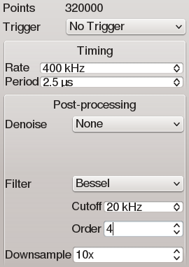
The interface provides some basic controls that determine the behavior of the NiDAQ device during the task:
- Trigger allows to select a device that should trigger the DAQ to start the task. If No Trigger is selected, then the task will be started by software trigger. The devices that appear in this list will be only those that have declared a connection to a PFI line on the DAQ for triggering purposes. These include Cameras with a triggerOutChannel configured, and Trigger devices.
- Rate Specifies the sample rate to use for all channels in the task. Period is merely the inverse of Rate.
Several post-processing options are available as well. These only affect the data returned by the DAQ; the outputs generated by the DAQ will not be affected.
- Denoise allows to select from a list of filters that remove noisy outliers.
- Filter allows to select from a list of high- or low-pass filters (Bessel or Butterworth)
- Downsample causes the data returned to be downsampled by either averaging groups of N samples (in the case of analog signals) or by sub-sampling every Nth sample (in the case of digital signals). For systems with large amounts of high-frequency noise, it is beneficial to oversample the signal (the sample rate must be more than twice the noise frequency), then downsample back to a reasonable sample rate, possibly in conjunction with a low-pass filter.
Stored data format
NiDAQ devices do not directly store data to disk. However, they do generate a standard metadata structure describing the device configuration whenever a Task is executed. Most devices that make use of the DAQ will opt to store this metadata structure along with any data they write to disk. The structure follows:
numPts: integer number of samples in the array (after downsampling; originally recorded numPts*downsampling)
rate: sample rate of the array data (also after downsampling; original rate was rate*downsampling)
holding: the output value assigned to the channel after the task completed
startTime: the timestamp (seconds since unix time epoch) at the beginning of the task
type: ‘ai’ | ‘ao’ | ‘di’ | ‘do’
downsampling: downsampling factor applied to the data after it was collected
- filterMethod: The filtering method that was applied during post-processing, if any.
- Other filtering parameters depend on filter type
denoiseMethod: The denoise method that was applied during post-processing, if any.