AxoPatch Devices
This device supports the use of the AxoPatch 200 amplifier. It requires a DAQ device to record from and output to each of the channels on the device. The following features are supported for the AxoPatch 200:
- Support for use with Patch module and Task Runner module.
- Assisted switching between recording modes. The AxoPatch 200 uses a manual switch to select between current- and voltage-clamp recording modes. When a module requires access to a specific recording mode, a dialog window pops up instructing the experimenter to set the clamp mode accordingly.
- Manages separate holding levels for current- and voltage-clamp modes; automatically selects correct holding value when switching between modes.
- Records from the gain channel on the amplifier and automatically scales electrode data accordingly.
- Records LFP channel output as meta-data of electrode recordings.
Hardware configuration
At a minimum, using AxoPatch devices under ACQ4 requires:
- DAQ analog inputs connected to the Mode, Gain, and ScaledSignal outputs on the AxoPatch
- A DAQ analog output connected to the command input on the AxoPatch
Optionally, the LFP output on the AxoPatch may be connected to a DAQ analog input.
Configuration Options
The following is an example device configuration for an AxoPatch 200 device:
AxoPatch200:
    driver: 'AxoPatch200'
    ModeChannel:
        device: 'DAQ'
        channel: '/Dev1/ai13'
        type: 'ai'
    GainChannel:
        device: 'DAQ'
        channel: '/Dev1/ai14'
        type: 'ai'
    LPFChannel:
        device: 'DAQ'
        channel: '/Dev1/ai15'
        type: 'ai'
    Command:
        device: 'DAQ'
        channel: '/Dev1/ao0'
        type: 'ao'
    ScaledSignal:
        device: 'DAQ'
        channel: '/Dev1/ai5'
        type: 'ai'
    icHolding: 0.0*pA
    vcHolding: -50*mV
The supported configuration parameters are:
driver must be ‘AxoPatch200’
- DAQ channel specifications for each of the AxoPatch channels that are connected to the DAQ:
- ModeChannel: channel connected to the Mode output.
- GainChannel: channel connected to the Gain output.
- LFPChannel: channel connected to the LFP output.
- Command: channel connected to the Command input.
- ScaledSignal: channel connected to the Scaled Signal output.
icHolding: The default holding current when the device is in current-clamp mode.
vcHolding: The default holding voltage when the device is in voltage-clamp mode.
Manager Interface
If an AxoPatch device is configured properly, a simple interface will appear in the manager module window:
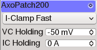
This interface allows the recording mode and holding values for current- and voltage-clamp to be configured. Any changes made to these values will immediately affect the state of the device.
Task Runner Interface
The TaskRunner interface for AxoPatch devices appears as a dock in the Task Runner module when a AxoPatch device is selected in the device list. This interface allows the design of stimulation waveforms and recording parameters for executing tasks.
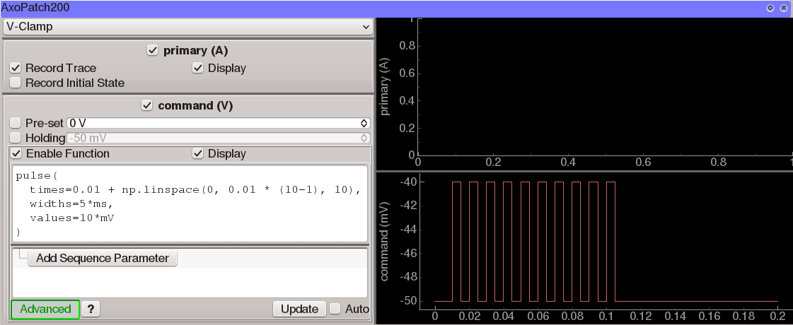
The left half of this interface consists of three main sections:
A list of operating modes (V-Clamp, I=0, I-Clamp Fast, I-Clamp Normal, Track). Running the task will require that the amplifier be set to the selected mode. If it is not, then a dialog will appear when the task starts, asking the user to set the mode accordingly.
Controls affecting recording from the primary output channel of the amplifier (Scaled Signal).
- Controls that determine the command output:
- Pre-set sets the voltage or current command immediately before the task begins, if the box is checked.
- Holding determines the voltage or current command that will be set immediately after the task finishes. If the box is unchecked, then the current holding value (as indicated in the Manager interface described above) will be used.
- A function generator that is used to specify the output waveform and sequence parameters.
The right half of the interface holds plot areas for displaying the recorded signal (top) and command signal (bottom).
Stored data format
AxoPatch tasks that store to disk will generate a single MetaArray file containing two columns: “command” and “primary”. Metadata are as follows:
- All DAQ configuration settings including sample rate, filtering, and downsampling.
- The AxoPatch operating mode (V-Clamp, I=0, I-Clamp Fast, I-Clamp Normal, Track).
- Current Gain and LFP settings.
- The standard function generator metadata structure.