MultiClamp Devices
ACQ4 supports the MultiClamp 700A and 700B amplifers on Windows via the Commander software available from Molecular Devices. Multiclamp Commander must be running before starting ACQ4. A MultiClamp device in ACQ4 represents only a single channel; to access both channels, simply configure two devices with the appropriate channelID strings.
MultiClamp devices support:
- Simultaneous input/output on one or both electrode channels.
- Recording all MultiClamp state parameters along with physiological data.
- Controlled mode switching VC <–> I=0 <–> IC
- Setting gain and signal selection for primary and secondary signals.
Note
ACQ4 handles MultiClamp holding values by setting the desired level on the DAQ command channel. The holding levels configured by the Commander software are separate and will be added to any holding level or output commands specified in ACQ4.
Hardware configuration
At a minimum, using MultiClamp devices under ACQ4 requires:
- A DAQ analog input connected to the primary output per MultiClamp channel
- A DAQ analog output connected to the command input per MultiClamp channel
- A serial (700A) or USB (700B) connection between the CPU and MultiClamp.
Optionally, a second DAQ analog input may be used to record the secondary output per MultiClamp channel.
Configuration Options
The following example is for channel 1 on a Multiclamp 700A. To use two channels, simply define a second device with the appropriate channelID string.
Clamp1:
    driver: 'MultiClamp'
    channelID: 'model:MC700A,com:3,dev:0,chan:1'
    commandChannel:
        device: 'DAQ'
        channel: '/Dev1/ao0'
        type: 'ao'
    primaryChannel:
        device: 'DAQ'
        channel: '/Dev1/ai10'
        mode: 'NRSE'
        type: 'ai'
    secondaryChannel:
        device: 'DAQ'
        channel: '/Dev1/ai9'
        mode: 'NRSE'
        type: 'ai'
    vcHolding: -50e-3
    icHolding: 0.0
    defaults:   # Optionally configure the default amplifier state.
                # The amplifier will be reconfigured with these options
                # every time ACQ4 is started.
        IC:
            HoldingEnable: False
            Holding: 0.0
            TestSignalEnable: False
            #SlowCurrentInjEnable: False
            NeutralizationEnable: True
            #OscKillerEnable: True
            PrimarySignalGain: 2
            PrimarySignalLPF: 20e3
            PrimarySignalHPF: 0
            OutputZeroEnable: False
            BridgeBalEnable: True
            BridgeBalResist: 15e6
        VC:
            HoldingEnable: False
            Holding: 0.0
            TestSignalEnable: False
            #SlowCurrentInjEnable: False
            #NeutralizationEnable: False
            WholeCellCompEnable: False
            RsCompEnable: False
            #OscKillerEnable: True
            PrimarySignalGain: 2
            PrimarySignalLPF: 20e3
            PrimarySignalHPF: 0
            OutputZeroEnable: False
            LeakSubEnable: False
The supported configuration parameters are:
driver must be ‘MultiClamp’
channelID: A string that identifies the MultiClamp device and channel to connect to via the Commander software. For 700A devices the string is formatted like
model:MC700A,com:3,dev:0,chan:1. For 700B devices, the string is formatted likemodel:MC700B,sn:00106780,chan:1. To determine the channelIDs available on your system, simply start ACQ4 with a MultiClamp device configured with an empty channelID string; an error message will be displayed containing the available strings.- DAQ channel specifications for each of the MultiClamp channels that are connected to the DAQ:
- commandChannel: channel connected to the command input.
- primaryChannel: channel connected to the primary signal output.
- secondaryChannel: channel connected to the secondary signal output.
icHolding and vcHolding: The default holding current / voltage when the device is in current-clamp / voltage-clamp mode. ACQ4 handles MultiClamp holding values by setting the desired level on the DAQ command channel. The holding levels configured by the Commander software are separate and will be added to any holding level or output commands specified in ACQ4. When ACQ4 switches the device between IC and VC modes, it always stops at I=0 in between to select the appropriate holding level.
defaults: A list of default values to assign to the MultiClamp Commander every time ACQ4 is started. This may be used to ensure that experiments always begin with a consistent configuration (especially gain and filter settings). Parameters are split up into IC and VC groups; see above for an example. For a complete listing of the parameters available, open a Console module and type the following:
dev = man.getDevice('ClampName')
dev.getState()
This will print the complete set of parameters currently active on the device. Note that the ‘Holding’ parameters in this context refer to the MultiClamp commander’s holding values; see icHolding and vcHolding above.
Note
To configure the default parameters specified in the IC and VC groups, ACQ4 must briefly switch the clamp mode to IC and VC during startup. The clamp mode will be set to I=0 after this configuration is complete.
Task Runner Interface
The TaskRunner interface for MultiClamp devices appears as a dock in the Task Runner module when a MultiClamp device is selected in the device list. This interface allows the design of stimulation waveforms and recording parameters for executing tasks.
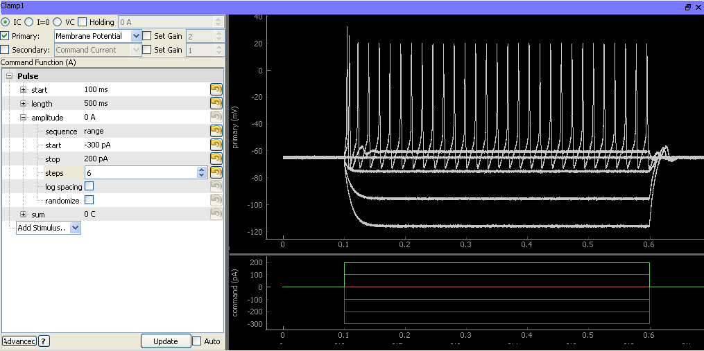
The left half of this interface consists of two main sections:
- Device configuration controls:
- Clamp mode (VC, I=0, IC). When the task starts, the amplifier will be swirched to this mode.
- Holding determines the voltage or current command that will be set immediately after the task finishes. If the box is unchecked, then the current holding value (as indicated in the Manager interface described above) will be used.
- Primary selects the primary output to use when the task starts. If the box is unchecked, then the value will be unchanged.
- Secondary selects the secondary output to use when the task starts. If the box is unchecked, then the value will be unchanged.
- Set gain changes the gain values for the primary and secondary channels, if checked.
Command function holds a standard function generator that is used to specify the output waveform and sequence parameters.
The right half of the interface holds plot areas for displaying the recorded primary signal (top) and command signal (bottom).
Stored data format
MultiClamp tasks that store to disk will generate a single MetaArray file containing three columns: “command”, “primary”, and “secondary”. Metadata are as follows:
- All DAQ configuration settings including sample rate, filtering, and downsampling.
- The standard function generator metadata structure.
- All MultiClamp state parameters including the clamp mode (VC / I=0 / IC), holding values, pipette offset, gain, filtering, bridge balance, and all compensation settings.